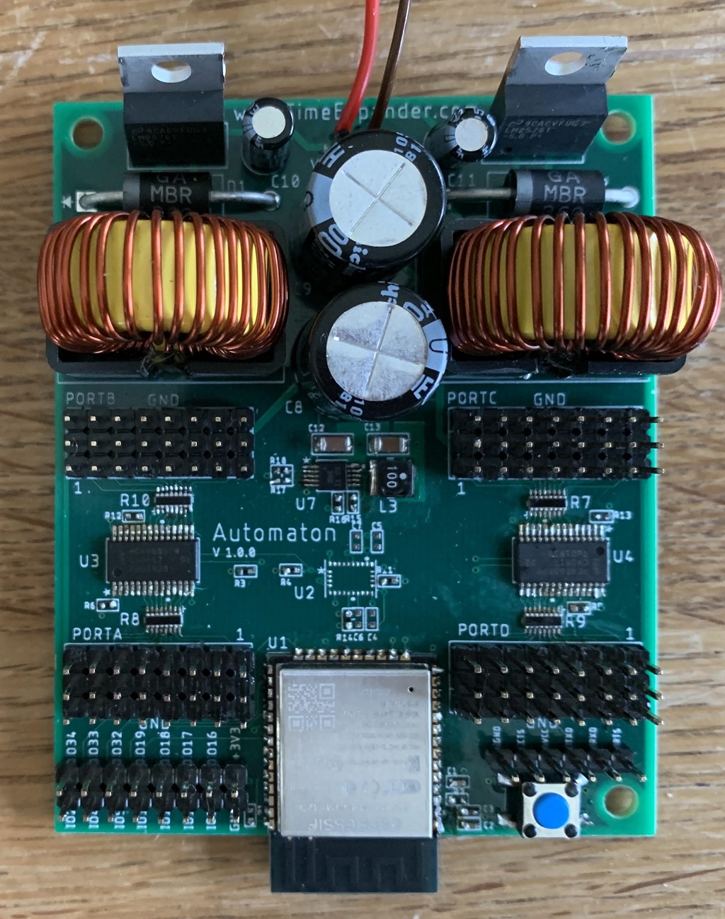
The Automaton
“The Automaton” is my take on how to do a low budget robot controller.
Tech specs⌗
- 6 - 45V input voltage range.
- Support for up to 32 servos with a maximum total current draw of 6A at 5V.
- 24Hz to 1526Hz PWM controller with 12 bit resolution.
- 240MHz MCU with WiFi and Bluetooth.
- 9DOF sensor fusion IMU that outputs absolute orientation angle at 100Hz.
- FTDI programming header.
- Expansion header with 14 available GPIO pins.
The design⌗
Power
LM2576 buck regulators supply power to the servos via two separate power rails. Each rail can provide up to 3A at 5V. The voltage input range is 6-45V, which allows the use of wide variety of battery configurations for powering the board.
I plan on using this board with micro or mini servos which will typically have idle currents in the 10mA range and operating currents (when moving) in the 100-200mA range. Bigger servos will require more power. Do not expect this board to be able to power 32 standard size RC servos.
A TPS62056 provides stable 3.3V power to the MCU and PWM controllers. This can supply up to 800mA, which should be enough to handle any current spikes caused by the rather power hungry MCU.
MCU
I recently fell in love with the Espressif ESP-WROOM-32 MCU, which can be clocked up to 240MHz. You also get WiFi and Bluetooth out of the box. It requires only 4 passive support components in order to operate. At $4 this is was a nobrainer choice.
PWM Servo Controller
I shamelessly ripped this part of the circuit from Adafruit’s 16-Channel 12-bit PWM/Servo Driver - I2C interface, but I don’t feel especially bad about this, since the Adafruit board is basically just a breakout for the PCA9685 LED driver.
I also doubled up on the number of channels, since a typical hexapod or biped will require more than 16 servos.
IMU
I decided to go for the BNO055, since I already have some experience with it from earlier projects. This is a 9DOF IMU that does sensor fusion and provides you with an absolute orientation angle at 100Hz. This is an optional extra, that may come in handy for controlling a robotic biped, where you can’t safely rely on static balancing alone.
Firmware
The board is programmable via the FTDI header. Pressing the button on power up will force the board into programming mode. It can then be programmed in PlatformIO using either the Espressif or the Arduino framework.
Stuff that I forgot⌗
- Include indicator LEDs for servo power rails and 3.3V rail.
- Expose the SDA/SCL signals on expansion header.
- Reverse polarity protection for the input power.
Stuff I can probably improve⌗
- Shrink the PCB somewhat. The PCB is currently a 4 layer 65 x 80mm board. The size is probably acceptable as it is, even for a small biped., but smaller is alwasy better, since it imposes less physical constraints on the robot design.
- Add support for a speaker / voice module.
The budget⌗
The approximate (low volume) parts cost for this board is 34 USD if you don’t need an IMU. Including the IMU wil add approximately 11 USD to the total cost.
Manual PCB assembly is doable if you have access to a microscope and a decent soldering station. All the passives are 0402, but the pitch of the resistor arrays and PWM controllers is a bit on the small side.
Versions⌗
I am also planning on doing a Dynamixel-version of this board. I haven’t done a detailed design yet, but it will be a much simpler and much smaller board. This version will not require the initial buck regulator stage, but will instead run directly from 11.1V LiPo cells. It will also require a significantly lower number of connectors, since the Dynamixels are serial servos.
I haven’t decided yet, but I just might add XBee support, since this would allow me to use the Arbotix hand controller for communicating with the robot.
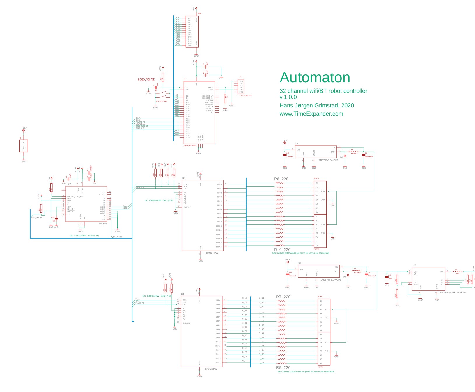
Schematics⌗